Building it
It's not that difficult to build your own DSPdap hardware. Note that you will need some experience in electronics and SMT soldering.
First download the latest hardware release from http://sourceforge.net/dspdap. Have a look at the schematics, the bill of materials and the PCB layout.
PCB
The DSPdap PCB is a relatively complex so get it fabricated from a decent PCB fabricator in your locality. Don't go to the big guys since they won't encourage you for your small quantity requirement. Just make sure that the vendor can fabricate the PCB. It is a 2 layer Plated Through Hole (PTH) PCB with 0.9mm via pads and 0.2mm minimum track width. Make sure you make the PCB with the solder masks and the silk-screen layers. The release contains both PDF and PRN files for the PCB layers. Use the high resolution PRN files to fabricate the PCB
After you get the PCBs, test the PCB connections manually against the schematic. This is to make sure none of the PTH connections are open. You will also get a better understanding of the PCB layout, which will help you while electrical testing.
Getting the Components
While the PCB is being fabricated it is a good time to buy the components. All the components listed in the Bill of Materials are required to build DSPdap. You will find almost all the components on Digikey or Mouser. It is wise to buy some spare components that can be handy if any component is lost/damaged.
You could get the CompactFlash card at your camera accessories dealer or buy one online from SterlingTek. A 64MB card costs around $5. Get as much capacity as possible in your budget.
WARNING !!!
Do not use your camera's CompactFlash card with DSPdap since you will loose all the data on the card. The card will work with DSPdap but is not guaranteed to work with your camera again. It is best to buy a separate one for DSPdap.
Soldering
Soldering is the second most important step. Soldering the ICs and the CompactFlash connector can be tricky and needs some level of SMT soldering skills. If you are new to SMT soldering, first try your hands on low cost dummy components and PCBs before soldering the DSPdap board. You will need a good fine-tipped SMT soldering gun, good solder wire, solder assist fluid and a de-soldering pump to do the job. Do refer to this SMT soldering tutorial
Before starting out to solder, read the entire documentation at least once. Follow the below mentioned order for soldering. We solder the components stage by stage and then test the functionality of each stage. It is easier to debug the hardware this way compared with completely assembling the board and then testing.
Boost Converter
Soldering
We'll start off by soldering the Boost converter stage. Solder the boost converter IC (U3) and all surrounding components required to get it working, including the battery connector (P4). While building and testing it is recommended to use a 3V DC power supply to power the board instead of batteries. Once things are finalized we can switch to batteries. Don't forget solder SW1, R7 and place jumper JP1, else converter won't power up.
Testing
First check the resistance between the pins of battery connector (P4). It should measure in the order of a few 10s of Kilo-Ohms (80~130K). A very low impedance between these pins indicates a fault and needs to be rectified before powering the board. Apply 3V DC power to the board through the battery connector (P4). Measure the voltage across C4. It should be 0V. Now momentarily press SW1 switch. Voltage across C4 should shoot up to 3.3V and voltage at PGOOD line should be 3.3V. Now try switching off the converter by shorting the PGOOD line to ground using a short wire. Now voltage across C4 should drop to 0V. That's it the boost converter is working fine.
Now repeat the above procedure after reducing the input voltage to 1V. Results should be the same, because it's a boost converter, isn't it!!
Step-down Converter & SVS
Soldering
Solder the step-down converter IC (U4), the SVS IC (U5) and associated components. Place jumper JP4 but not JP5.
Testing
Apply 3V DC power to the board. Depress SW1 and measure VCC, CVDD and RESET lines. VCC should be 3.3V, CVDD should be 1.6V and RESET should be 3.3V. Now Place JP5. This should bring RESET line to 0V. Remove JP5. This should bring back RESET to 3.3V. Great!! These two stages are working fine.
Low Drop-Out Regulator
Soldering
Solder the LDO IC (U6) along with the associated components including the USB port (P2), diode D1 and transistor (Q1). Place jumper JP2.
Testing
Power up the board by connecting a USB cable between the DSPdap board and a PC which has been turned ON. Measure the voltages at VBUS, VCC and CVDD. VBUS should be 5V, VCC should be 3.3V and CVDD should be 1.6V. Now turn on the 3V DC supply at P4. Measure the voltage at PGOOD line. It should be 0V indicating that the boost converter is off.
DSP and Codec
Soldering
The power stage being fully functional, it is safe to solder the DSP and the codec. First solder the DSP, then the codec and finally all the remaining components. After soldering, do a thorough inspection of all the soldered pins to see for any shorts or dry solder. Clean the PCB with isopropyl alcohol to remove any flux residue.
Testing
Check the resistance between VCC and ground lines. It should be a few Kilo-Ohms (8~15K). Place jumper JP2. Place jumper JP6 on position 2-3 for USB boot mode. Remove all other jumpers for now.
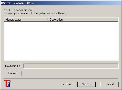
The simplest way to check if the DSP is working is to start it in USB boot mode and check if it enumerates on the host PC. First download the USBIO utility and install it. Run the USBIO Installation Wizard and click "Next".

USBIO Wizard screen
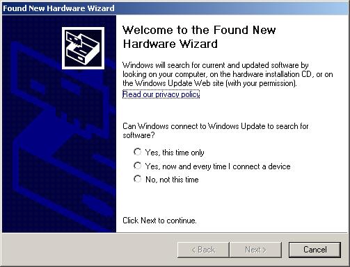
Now plug the DSPdap hardware to the PC's USB port. You should get the Windows New Hardware found screen. Click on "Cancel".

Windows New Hardware Found screen
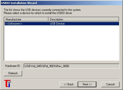
Click the Refresh button on the USBIO wizard. It should list a device with VID=0451 and PID=9001 or 9003. The DSP is functional. Congrats!!

USBIO Wizard: device found
Functionality Testing
It would be nice to have a board test routine that would test all the peripherals on the DSPdap board. There is no such test routine for now. The only way to achieve functionality testing is to run the latest firmware on the board and check if it works. Follow the Firmware procedure carefully to program the DSPdap board. But first, take a break!! You're almost through with the toughest part.
If you have any problems, doubts or suggestions you can post them at the DSPdap Project's forums page.


