Overview
The board is really dumb without the appropriate software. We will use three firmware files for this project.
- DSPdap-flash - The EEPROM flasher : this firmware does the serial EEPROM programming
- DSPdap-bootloader - The Bootloader : this firmware bootloads the player firmware from CompactFlash
- DSPdap-player - The Player application : this firmware is the player application
Since the EEPROM is not large enough to store our player firmware, we will store it on CompactFlash instead. There's plenty of room there for our 80KB firmware. It is this player firmware that does all the magic.
We use a small bootloader program to load the player firmware from the CompactFlash card into the DSP. This bootloader program must reside in the serial EEPROM. It is the first program that is executed when the DSP powers up.
The DSPdap-flash program is only required for flashing the bootloader program into EEPROM. It is not required otherwise.
Firmware Programming - The full procedure
The firmware programming is a bit lengthy on a virgin board. But once the bootloader has been programmed, re-programming the player firmware is quite easy.
Follow both procedures (A) and (B) if you are programming a virgin board or if you want to update the bootloader firmware. Follow only procedure (B) if you have accidentally deleted the player firmware or replaced the CompactFlash card.
(A) - Flashing the Bootloader
1) Download the latest firmware binaries from http://sourceforge.net/projects/dspdap
2) Download the USBIO demo utility from Thesycon and install it.
Make sure JP1, JP2, JP4 and JP7 are placed whereas JP3, JP5 and JP7 are removed. Place JP6 on position 2-3 for USB boot mode. The batteries need not be connected while programming since we will power up through USB.
3) In this step we register the USBIO drivers for the USB bootloading device. Skip to step 4 if you have installed USBIO drivers for VendorID:0x0451 & ProductID:0x9001.
Start the USBIO installation wizard and click "Next".
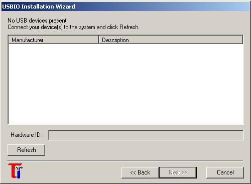
USBIO Wizard screen
Plug the DSPdap hardware to the PC's USB port. You should get the Windows New Hardware found screen. Click on "Cancel".
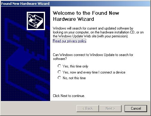
Windows New Hardware Found screen
Click the "Refresh" button on the USBIO wizard. It should list a device with VID:0x451 and PID:0x9001 or 9003. Select the device and click "Next". Complete the wizard and finally click "Finish". This completes the USBIO driver installation for the USB bootloader of the DSP. Disconnect the USB cable.
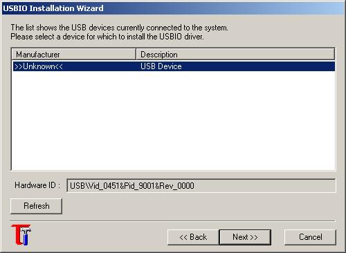
USBIO Wizard: Device found
4) In this step we will download the EEPROM programmer firmware (i.e. dspdap-flash) through USB.
Start the USBIO Demo Application. Connect the USB cable. The USBIO application should now show "Device0" in its device list. Click the "Scan for USBIO devices" button. This should show the devices Vendor and Product IDs in the output window.

USBIO Application: Device found
In the Configuration tab, set the "Conf. Desc. Index" as "0" and click Set Configuration.
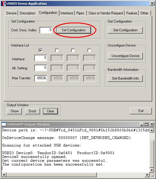
USBIO Application: Set configuration
In the "Pipes" tab, click on the "Read from File and Write to Pipe" button.
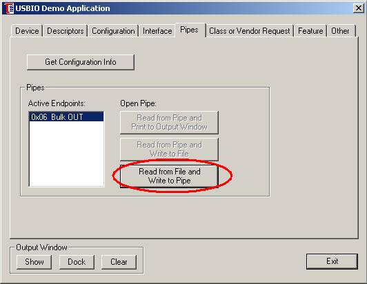
USBIO Application: Pipes
In the "Write from File to Pipe" tab, select the location of the dspdap-flash.bin file, make sure "Rewind at end of file" is unchecked and click "Start Writing".
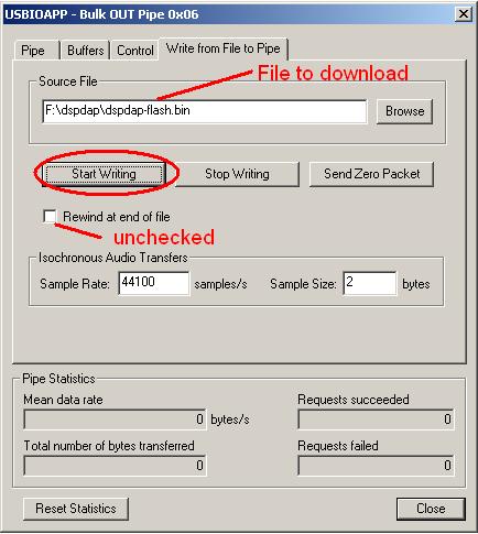
USBIO Application: Write to pipe
The writing should complete in a fraction of a second and the LED on the DSPdap board should start blinking. The device then automatically disconnects itself from the USB and re-enumerates as a device with VID=0x0451 and PID=0x9003. If the Found new hardware screen pops up then click on cancel and follow the USBIO installation wizard to install the USBIO drivers for this device. Do not disconnect the device. Follow step 5.
5) In this step we will send the dspdap-bootloader binary over USB for flashing to the EEPROM.
In the USBIO application, you should now get a device listed with VendorID:0x0451 and ProducID:0x9003. Open the device and set configuration 0. Now in the Pipes tab you should see 2 endpoints, Bulk OUT endpoint 0x02 and Bulk IN endpoint 0x82. The OUT endpoint is used to send the data to the DSPdap board whereas the IN endpoint is used to read data from it. The flash firmware we just programmed, expects the binary to be flashed to the EEPROM on the OUT endpoint. It sends debug messages over the IN endpoint.
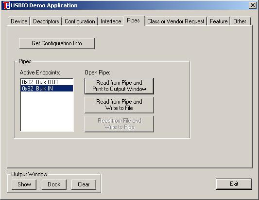
USBIO Application: 2 endpoints
Select the "Bulk IN" endpoint and click "Read from Pipe and Print to Output Window". Then select the "Read from Pipe to Output Window" tab, make sure "Print to Output Window" is checked and click on "Start Reading"
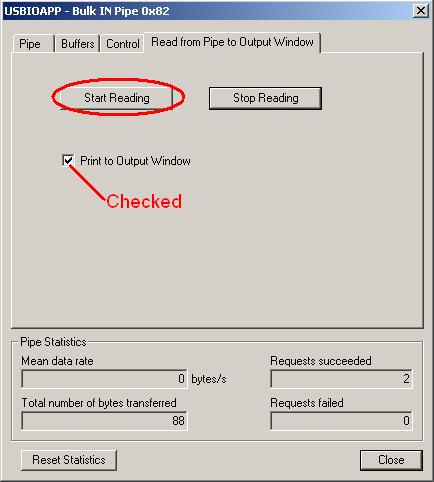
USBIO Application: Reading the IN endpoint
Without closing the Bulk IN window, see the USBIO output window. It should show some messages as shown below. Closing the Bulk IN window will stop the reading process, so keep it open.
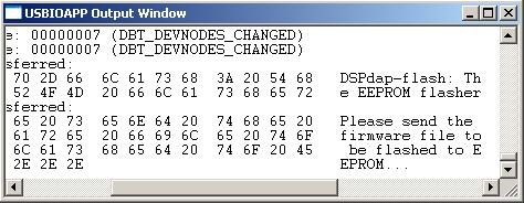
USBIO Application: USBIO Output window
Now we will send the dspdap-bootloader firmware to be flashed to the EEPROM. In the USBIO main window, select the Bulk OUT endpoint and click on "Read from file and Write to Pipe". Then select the "Write from File to Pipe" tab. Choose the dspdap-bootloader.bin file as the source file. Make sure "Rewind at end of file" is unchecked. Click on "Start Writing".
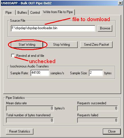
USBIO Application: Writing the Bootloader firmware
This should start the flashing process. Notice the messages on the Output Window. You should get a series of "Write passed" messages. When the messages stop, check the "Total number of bytes transferred" in the Bulk OUT window. It should match with the dspdap-bootloader.bin file's size. The bootloader flashing process is now complete. Disconnect the USB cable.
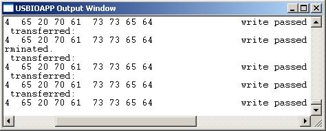
USBIO Application: USBIO Output window
(B) - Loading the Player firmware
Now we have the bootloader in place but we don't have the dspdap-player firmware on the CompactFlash card. This procedure will restore the player firmware. The logic is to bootload the board with the player firmware, so that it starts functioning as a USB pen drive. Then we copy the player firmware to it.
1) Put the board in USB boot mode by placing JP6 on position 2-3. Make sure JP1, JP2, JP4 and JP7 are placed whereas JP3, JP5 and JP7 are removed. The batteries need not be connected while programming since we will power up through USB.
2) Make sure the CompactFlash card is inserted properly.
3) In this step we USB bootload the board with the player firmware binary (dspdap-player.bin).
Start the USBIO application. Plug the player to the USB port. You should get a USBIO device (i.e. device0) in the application's device list. If you do not get the device or get a Windows New Hardware found message then follow the USBIO installation wizard as mentioned above in step 3.
Open the device and set configuration 0. In the Pipes tab, click the "Read from file and write to pipe" button. Then in the "Write from File to Pipe" tab, select the dspdap-player.bin file. Make sure "Rewind at end of file" is unchecked. Click on "Start Writing". The writing should complete in an instant and the player should enumerate as a USB mass storage device.
Windows XP/2000 should automatically detect and install the mass storage driver and the disk driver. You should then be able to see a Removable disk drive in "My Computer". This disk drive is nothing but the CompactFlash card on the DSPdap player. If the drive is not formatted using FAT32, format it using FAT32 filesystem. The player does not support FAT16 and other file systems. Make sure you backup the data on the card before doing so.
4) In this step we copy the player firmware to the CompactFlash card.
In Windows explorer, open the Removable disk drive corresponding to the DSPdap player. Copy the dspdap-firmwar.bin file to the root directory of this drive. Rename it to "firmwar.bin". NOTE: there is no 'e'. You can mark it as a hidden file to prevent accidental deletion. Deleting this file will prevent the player from starting up and you'll have to follow procedure (B) again.
Safely remove the USB hardware, by clicking the small removable drive icon in the windows taskbar and choosing "Safely remove Mass Storage Device". Disconnect the USB cable.
5) In this step we restore the player to I2C boot mode.
Move jumper JP6 to position 1-2 (i.e. I2C boot mode). The firmware programming procedure is complete. Woh!!!
The Best Part - Playing some Music!!
First we need to download some music files to the player. This is as simple as using a USB pen drive.
Plug the player to the USB port. You should straight away get a Removable drive in "My Computer". Copy some MP3 files to the root directory of the player's drive. Folders are not yet supported in player mode. But you can create folders to store data. The music files within folders will not be played. Disconnect the player from USB after following the Safe Hardware Removal procedure.
Plug in the headphones and click on the "Play" button. You can use the Volume up/down buttons to change the volume and the Next/Previous buttons to change the tracks. Enjoy the music!!
If you have any problems, doubts or suggestions you can post them at the DSPdap Project's forums page.


